Earth Continuity Limit
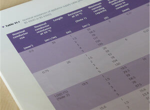
The limit for the Earth Continuity Test is (0.1 + R)Ω. Where the R value is the resistance of the protective conductor (earth wire) within the supply cable. In practice when PAT testing, measuring the actual resistance of the earth wire within the cable is impractical, therefore the R value is usually calculated using Table V1.1 in the IET Code of Practice.

| CSA mm2 | Resistance Ω/m |
|---|---|
| 0.5 | 0.039 |
| 0.75 | 0.026 |
| 1.0 | 0.0195 |
| 1.25 | 0.0156 |
| 1.5 | 0.0133 |
| 2.5 | 0.008 |
| 4 | 0.005 |
Table V1.1 in the appendix of the IET Code of Practice, page 134, gives the nominal resistance values for a variety of cable sizes and lengths. The resistance values are in mΩ (milliohms), so need converting to Ω before using the (0.1 + R)Ω formula. Our simplified version of the table (Fig.2) gives the resistance in Ω per meter.

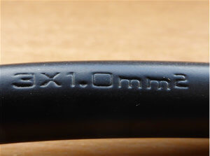
The cable size, cross-sectional area (CSA), is usually marked on the outer sheath. The example in Fig.3 shows a three-core cable with a CSA of 1.0mm2 per conductor. Therefore the maximum earth continuity limit for an appliance fitted with 3m of this cable would be: (0.1 + (3 X 0.0195))Ω = 0.16Ω.
High Earth Readings
Earth continuity readings higher than the (0.1 + R)Ω limit are often due to problems with the test procedure, rather than the appliance itself.

increase contact resistance
Contact Resistance
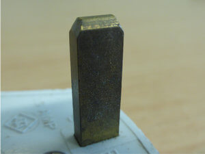
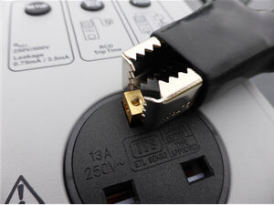
The contact resistance between the test lead and appliance case, or the appliance plug and test instrument, can significantly increase the measured resistance. The low current earth test (soft test) is particularly susceptible to the effects of contact resistance because it has less power to break through any oxidation layer on the plug or case. Cleaning the earth pin of the plug with an abrasive paper and making sure the test probe is making good contact with the metal surface will often reduce the earth continuity reading. Pay particular attention to where the test probe or clip is placed. For example, when testing a kettle, putting the test clip on a heating element without breaking through the limescale will increase the resistance significantly. If possible use the high current continuity test (hard test) to reduce problems with contact resistance.

Test Lead
The resistance of the test lead should also be taken into account. This can be measured by directly connecting the test lead to the socket on the tester. An earth pin from a spare plug can serve as a useful contact point for the test probe or clip. An allowance should be made for the measured resistance of the test lead. Some test instruments have the capability to null the test lead resistance. This feature records the measured resistance of the test lead and automatically accounts for it when calculating the total resistance.
Casual or Fortuitous Contact
The IET Code of Practice describes a situation where a Class I item may have metal parts that are not directly earthed but will provide a continuity reading because they are in contact with an earthed metal part. Connecting the test lead to metal that is not directly earthed will usually give a higher reading. For example, the case of a fridge is earthed because it contains electrical components such as the compressor, light, thermostat etc. The fridge door however does not usually house any electrical components and therefore does not require an earth connection. In this example, the fridge door is in ‘casual or fortuitous contact’ with an earthed metal part. Connecting the test lead to the door is likely to give a higher reading than if connected to the main case of the fridge.
"Unearthed metal may be in casual or fortuitous contact with the earthed metal. A continuity test made to this 'unearthed' metal may give misleading results." IET Code of Practice
If you are looking to learn more about electrical testing, we regularly run PAT testing courses at various venues across the country.